Context: I wanted to stretch my skills outside of web development, and work on a mechatronics project. I wanted a project that is challenging, but one I could have a first prototype for within a month, and that is anchored it into somewhat real problem. Watching a friend roast and pack coffee, I noticed a lot of time goes into measuring out 340g bags of coffee. The setup is slow and not ergonomic (an almost perfect case study for my industrial engineering classes back in the day!) so I thought it would be a good anchor for the project. The primary objective, however, is learning, and I don't intend to push the polishing past a working proof of concept.
Timeline: approximately 70 hours over two months of active work, though a lot of my modelling and thinking is done in the shower and in my sleep, which is not accounted for here.
Concept: The idea is to automate the dispensing of coffee to save on time and wrist strain. The initial concept is a feedback loop between an Arduino-powered scale and the motor powering the auger.
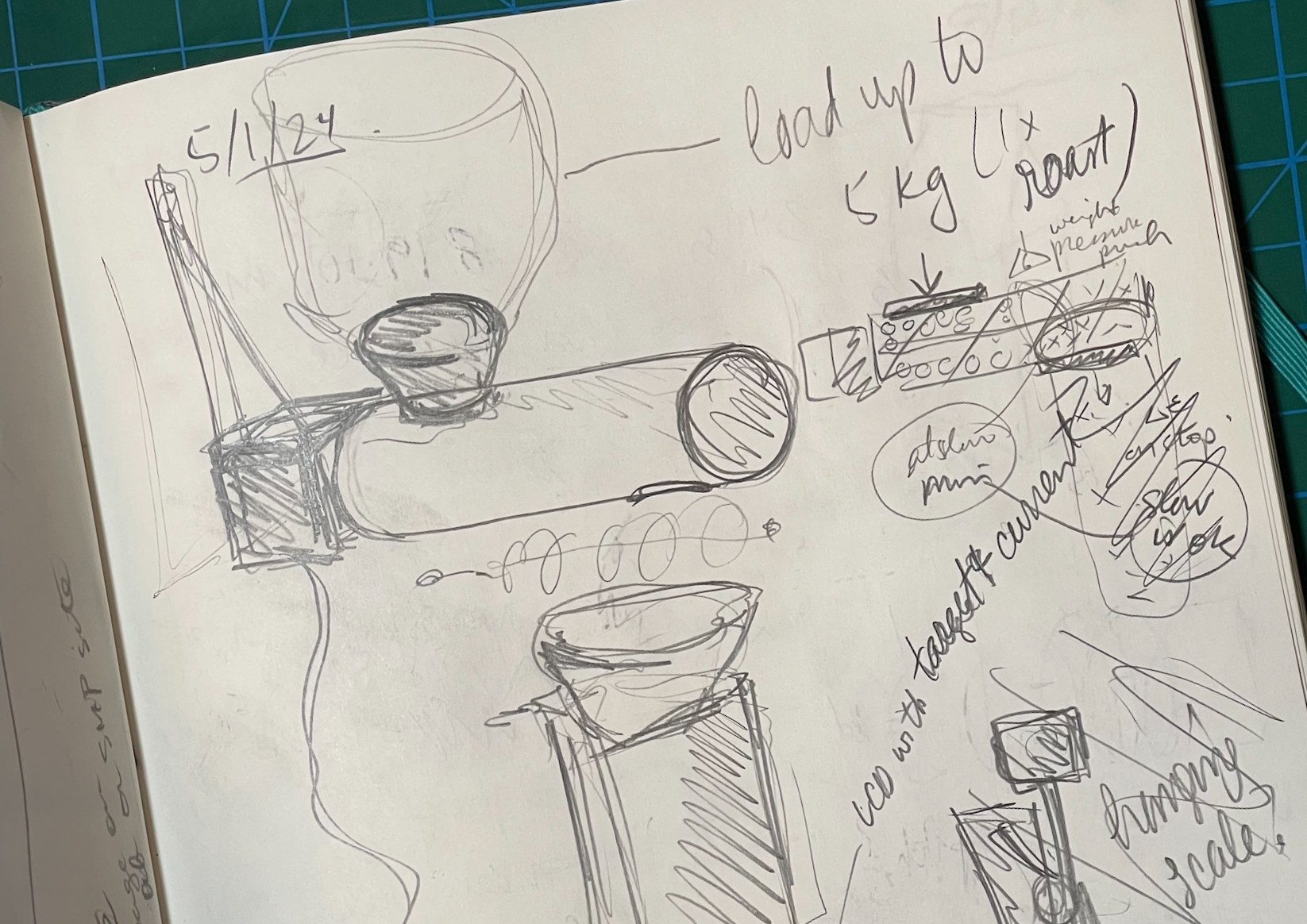
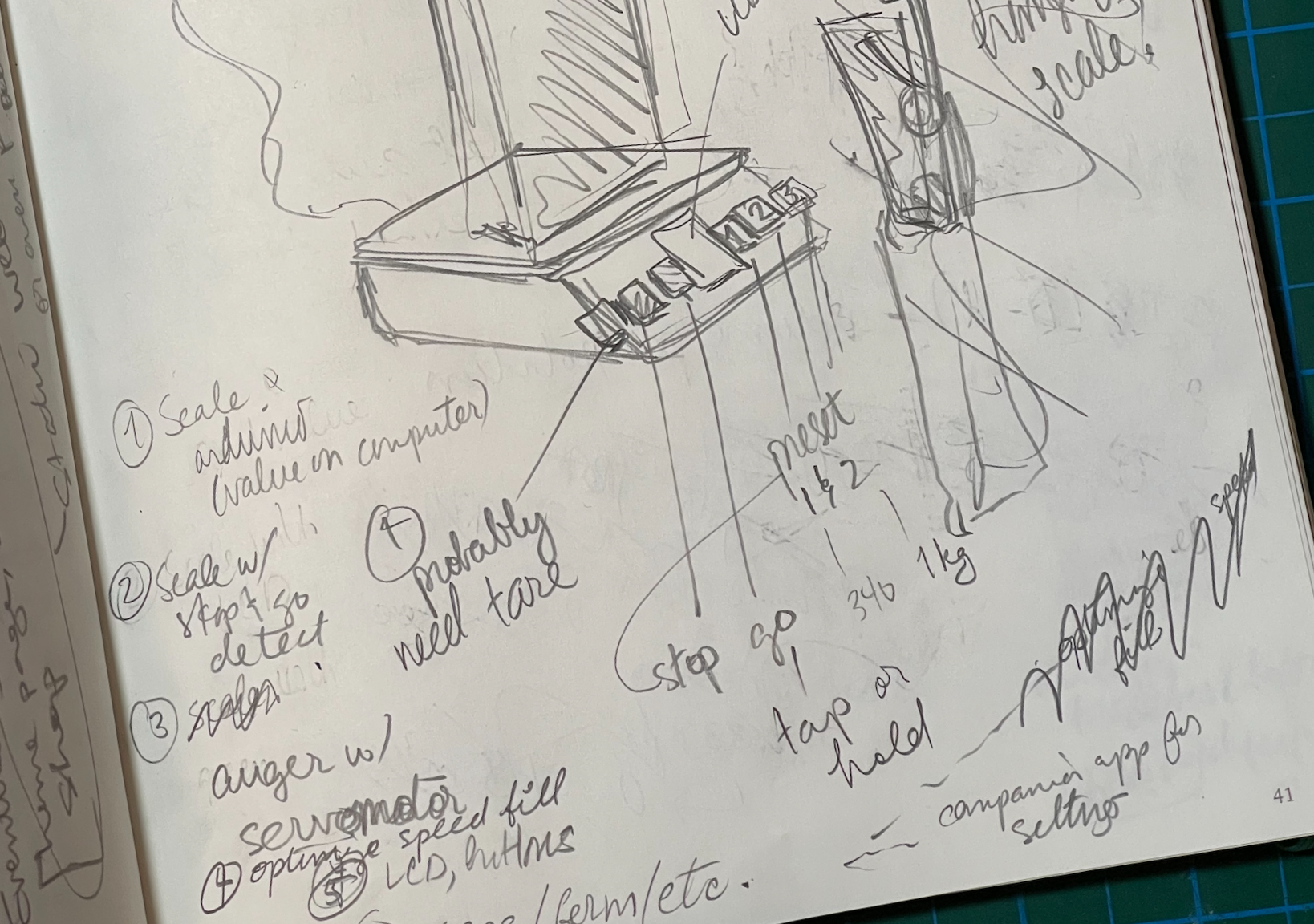
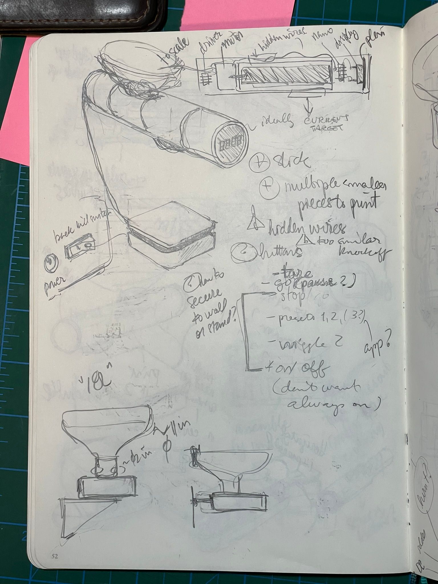
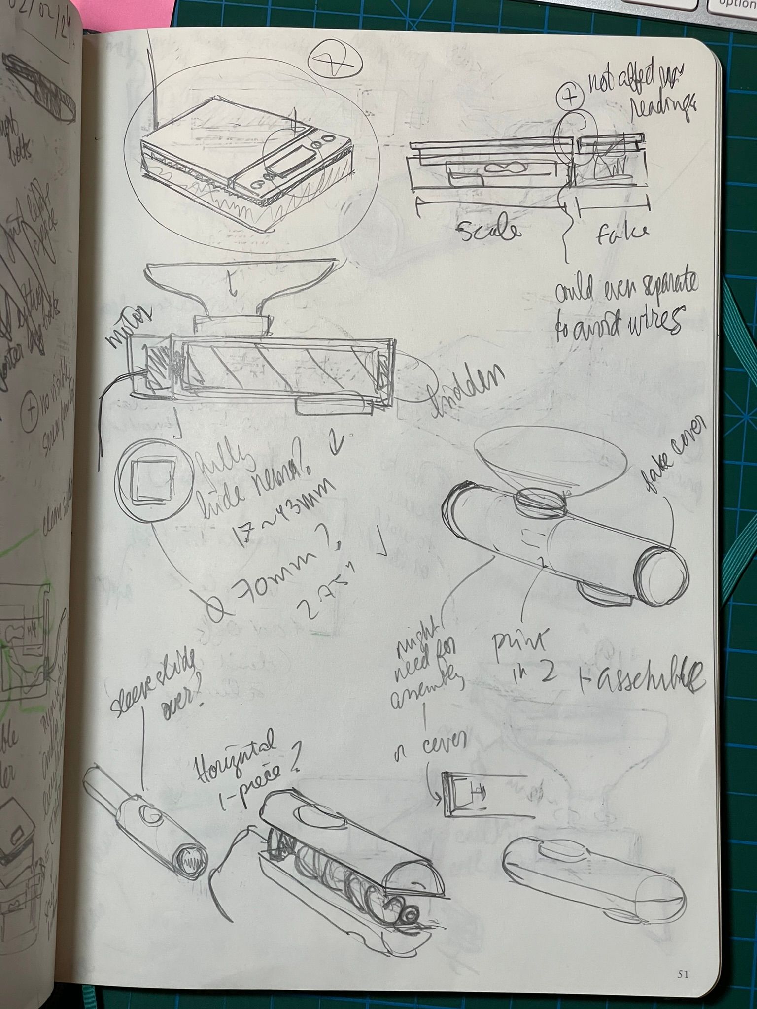
Early sketches of the overall idea
Process: My prior experience in mechatronics was very limited, so the biggest challenge was to orient myself within what is possible, more so than actually building the thing. I summarized the key parts of the process below, though the process was not linear, many things failed and I went back and forth between mechanical design and circuitry.
- Ideation: I started by reading tutorials around building the two subsystems I will need, the scale and the motor. The two are fairly well established in the Arduino world, so I knew I would have a load cell and a driver.
- Design: while I waited on the components to arrive from Ali Express, I iterated on mechanical designs for each individual subsystem, namely the auger, scale, outer shell, hopper, and housing for the electronic component.
- Simulation: I used Fusion 360 to build the full mechanical assembly and simulate the rotation of the auger, and I used an online Arduino simulator (Wokwi) to validate a very basic circuit.
- Prototype: I built and tested the individual systems one at a time as the components arrived, I started with a scale, then a basic motor circuit, then assembled the two together and so on.
- Testing: with the subsystems assembled and connected I was able to do a first full test of the complete system in the real world. The initial design needed to be revisited, of course, and more prototyping followed.
Technical details
Overall concept
In the initial steps, I knew I would need a scale and a dispenser. I went through several ideas on paper sketches to identify so initial parameters to guide me.
- I knew that the auger would need to reliably and precisely dispense 340g to 1kg at a time, so the feasibility auger design would be pivotal for the rest of the project. I narrowed down to a horizontal auger (see auger details below).
- I knew that batches of coffee would come in about 4-5 grams, so I would need either a hefty stand or a wall attachment (see below).
- I am limited by the bed size of my Prusa Mini, and I wanted to keep the amount of filament use reasonable (see below).
I researched existing commercial products and DIY projects. Commercial products were mostly complex and industrial, and DIY projects were mostly low speed cat food feeders. The closest product I found was the Acaia bean doser, which is meant to dispense much smaller doses, but it did heavily influence the initial design.
Auger
The auger was my starting point because I knew that the prototype hinged on being able to dispense 340g in a reasonable amount of time, i.e. considerably faster than doing it manually. I roughly estimated 30 seconds for dispensing one bag, and calculated the diameter and pitch of the auger thread. These measurements were very loose, I wanted to be approximately right, but thorough product and user research is day job material, and not a learning objective for me in this project.
I looked at auger designs in pharmaceutics and farming, and opted for a horizontal auger design, because it seems best suited for whole coffee beans (they flow better than powder and dirt, but won't drip like a liquid).
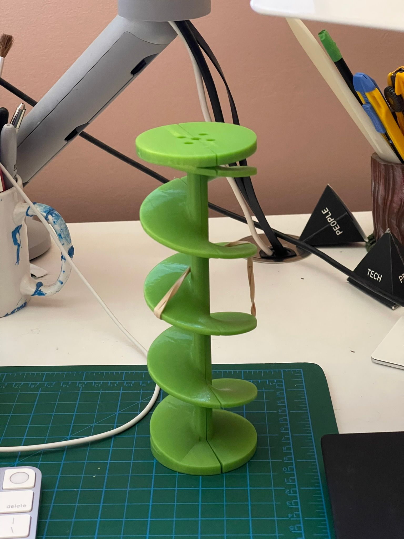
The auger design itself was fairly straightforward. Fusion 360 made it really easy to create the auger and tweak the size and pitch. I had recently worked on a modelling a custom thread, which was effectively the same as an auger.
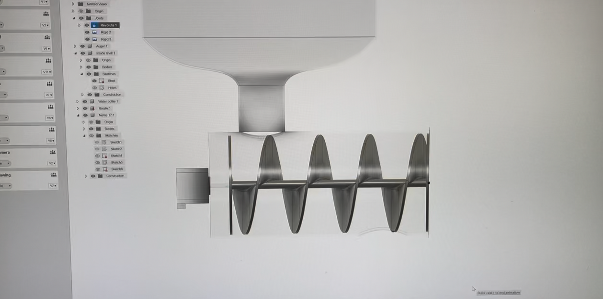
The 3D print of the auger was challenging. I was restricted to the bed size, and I didn't want to print the auger in multiple pieces. The pitch of auger is to aggressive to print vertically, and would require a ton of supports. I opted for printing it in two horizontal halves, following a great tip from Dave to also leave room for a steel rod, which I'm able to do with this approach.
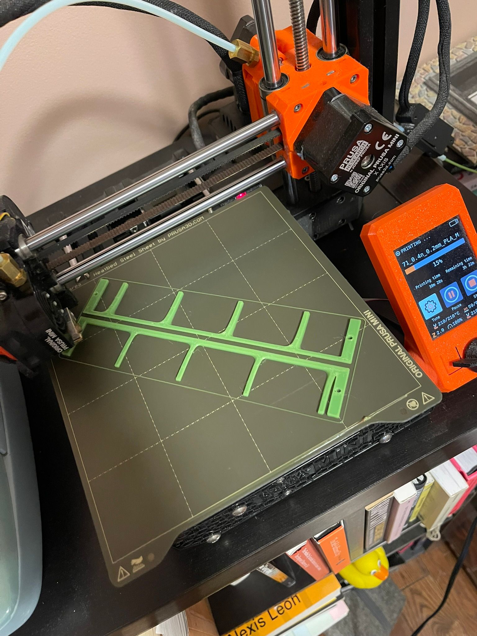
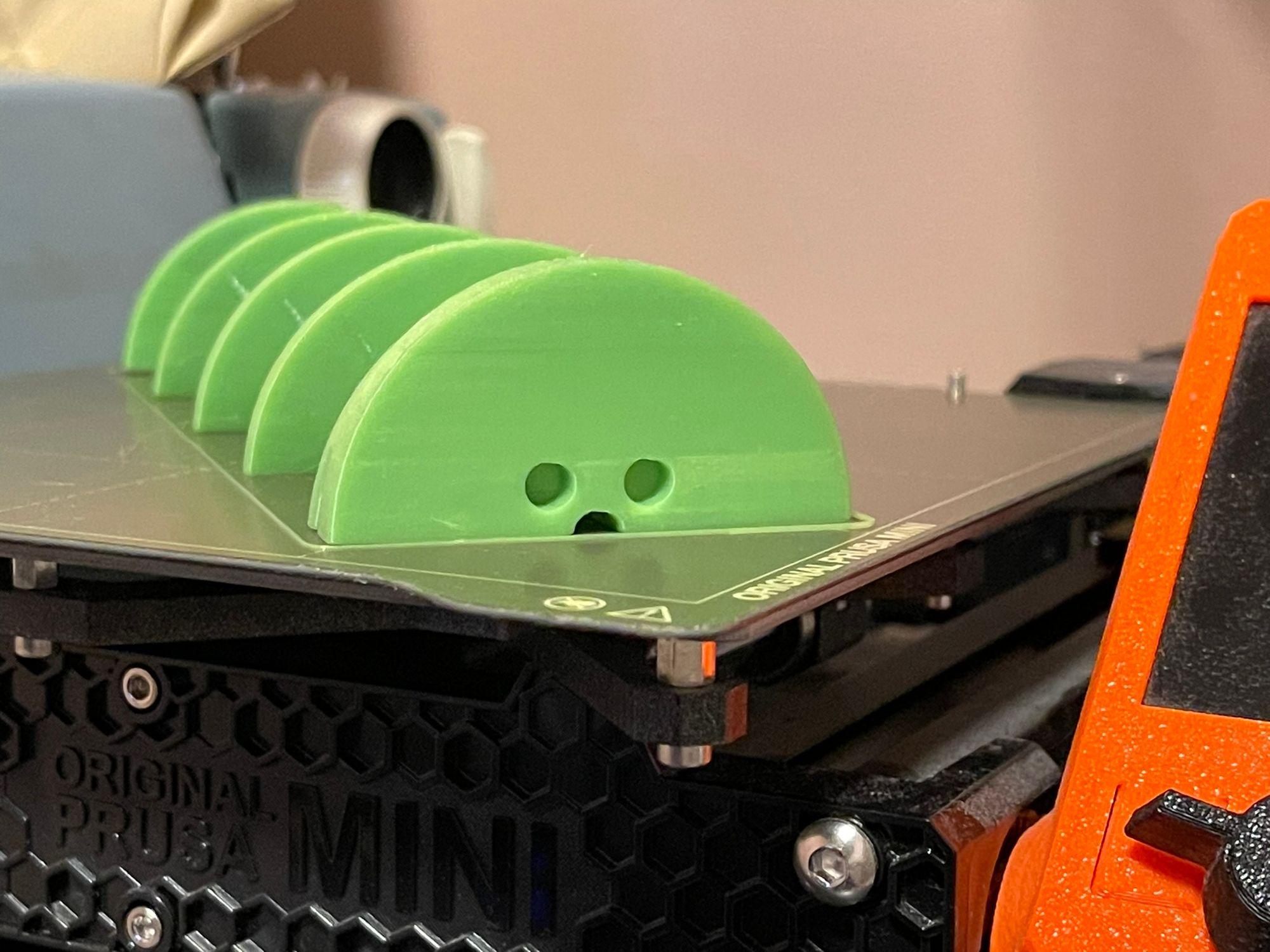
Photos of printing the auger
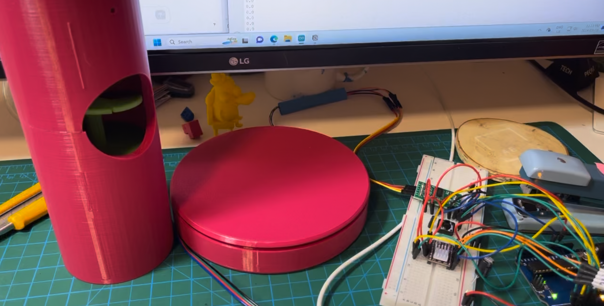
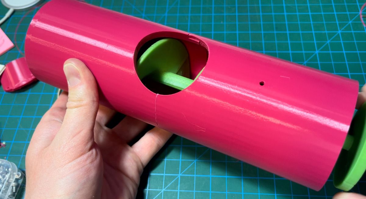
Shell assembly
The shell assembly was dictated by the size of the auger, but also by the constraints of the bed size of 3D printer. It took some time to come up with a good way to assemble it. I wanted to it work, but also to look good. There were many iterations, but they mostly happened while I sat on the couch staring at the wall, or during my very long neurodivergent showers.
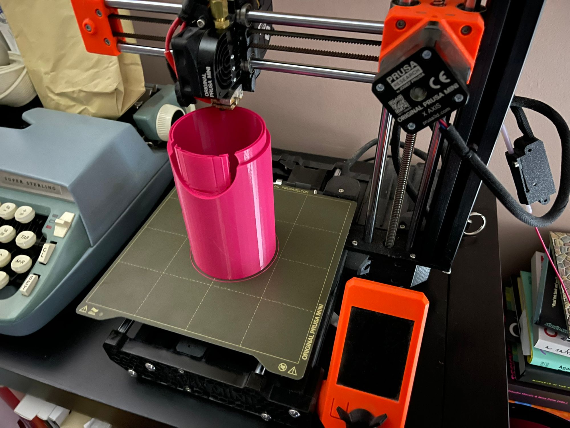
Left: where the printer froze at the power outage. Middle: inside the wall-side half of the shell where the motor is mounted. Right: 2 of 3 pieces assembled (missing the butt
There was a storm and a power outage partway through the 16-hour print of on of the larger pieces of the shell. I was able to adjust the design to salvage it, but it also made me realize that I could simply the design into a two-piece assembly, instead of the original "3-piece inner/outer sleeve" concept.
The restrictions over the print size turned out to be very useful constraints, because having smaller pieces to assemble made it very easy to add the motor and wiring. I also avoided permanently gluing pieces as much as possible, which was useful for diagnosing issues, and incrementally iterating on the design of the shell without reprinting a large piece.
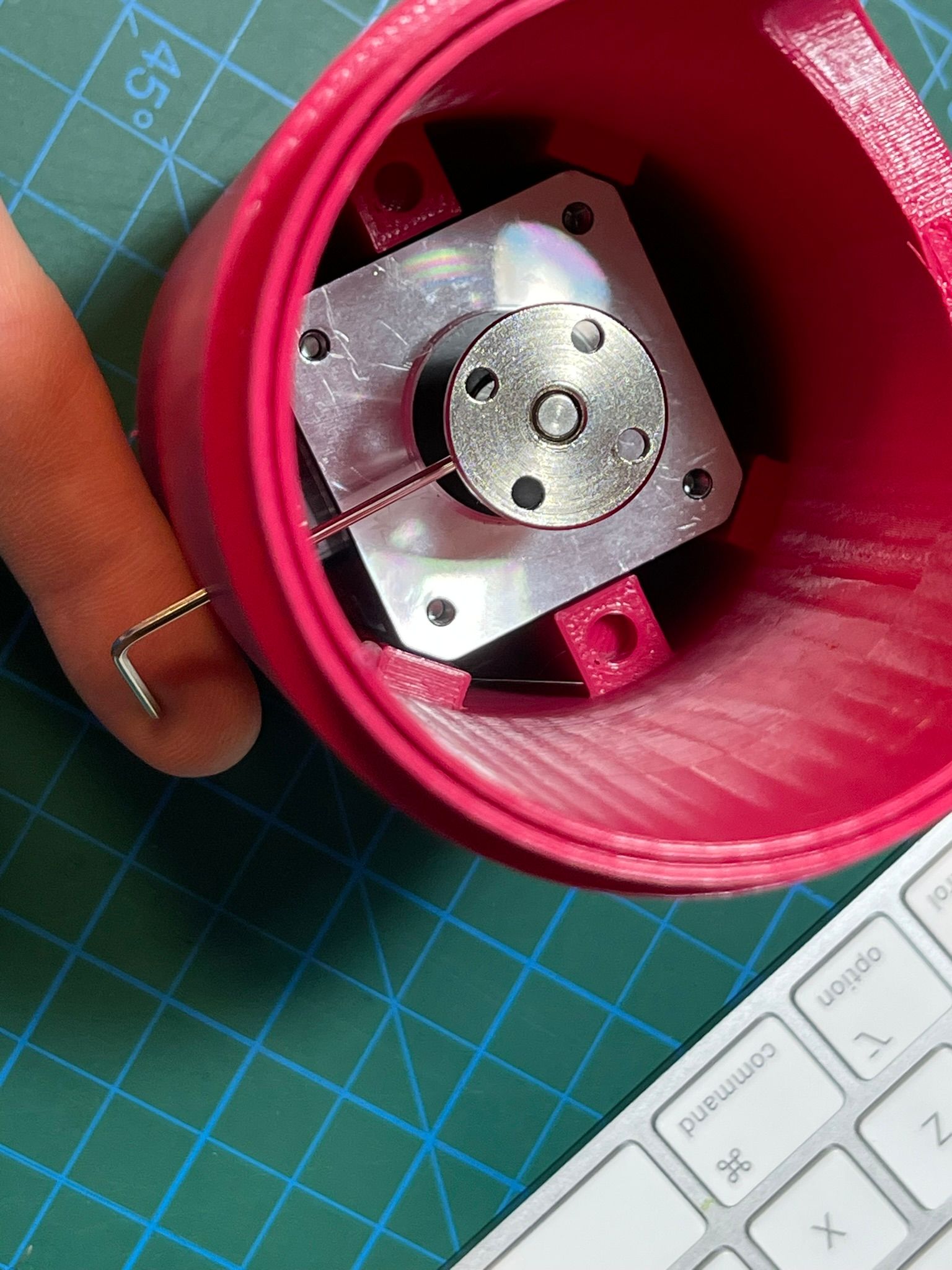
Motor assembly
I didn't know what motor I would need, in fact I didn't know much about motors at all. With lots of reading and the help of some friends, I narrowed down on a 1.2A NEMA 17 stepper motor. While I waited for it to arrive in the mail, I started designing the assembly.
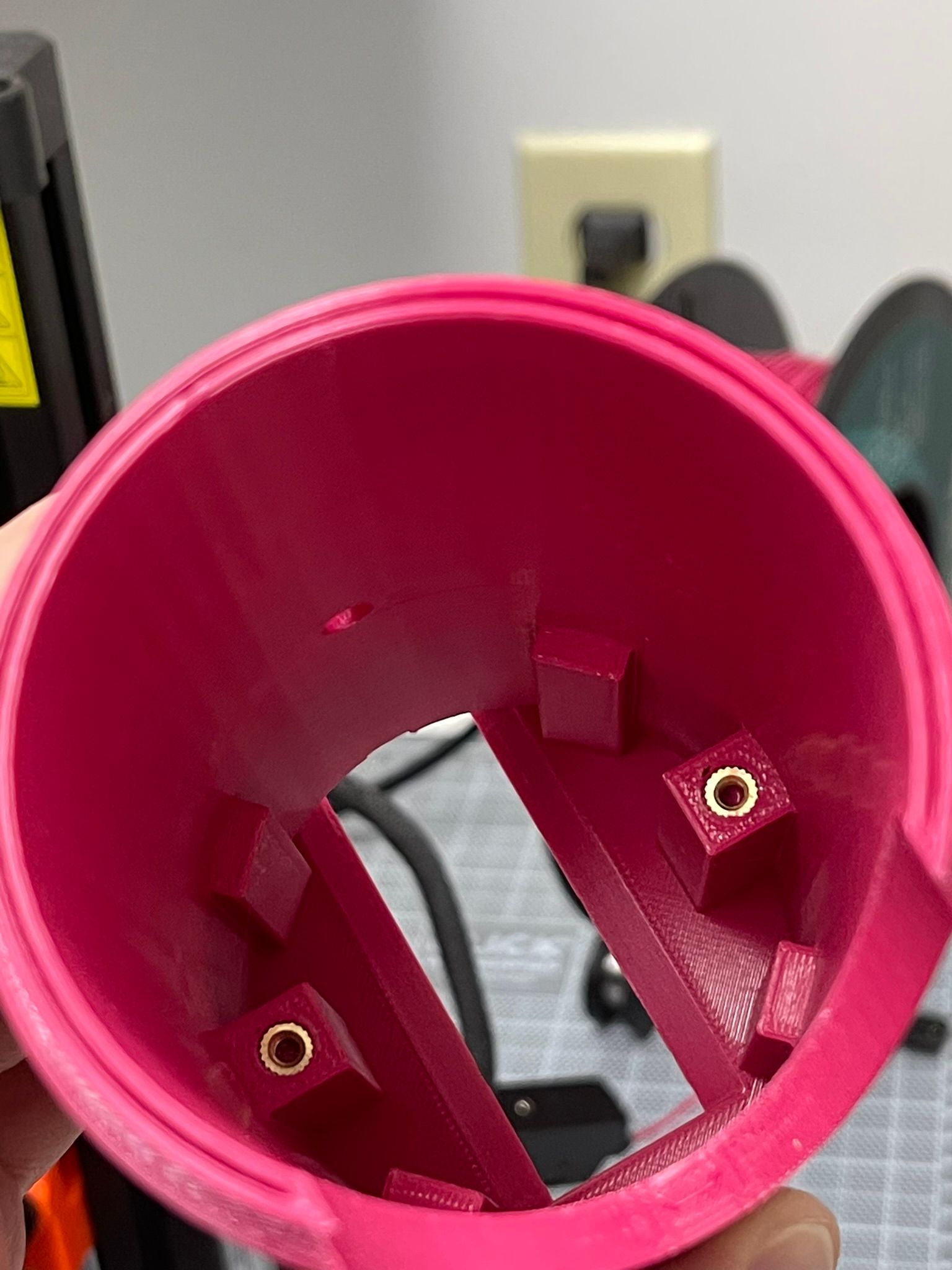
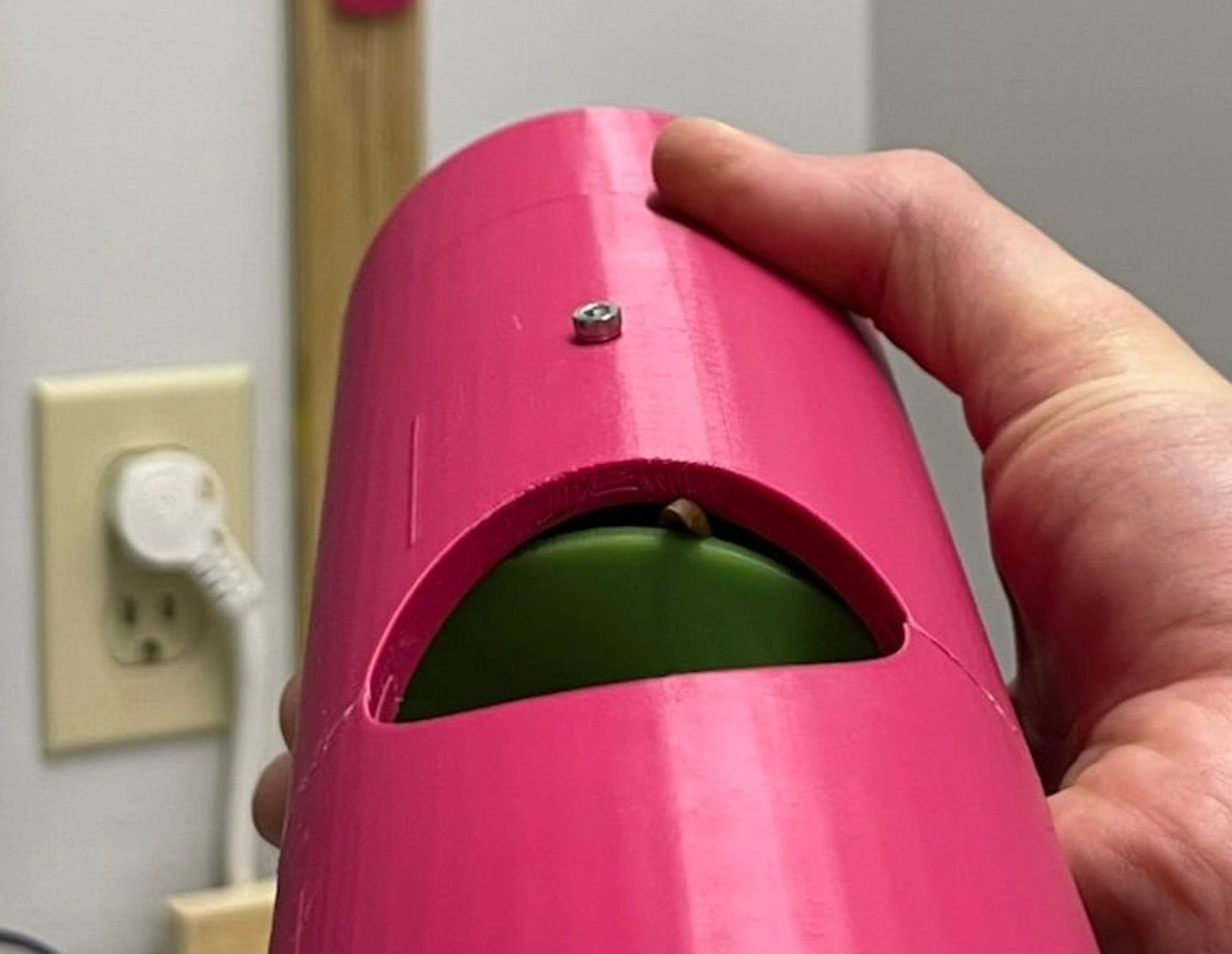
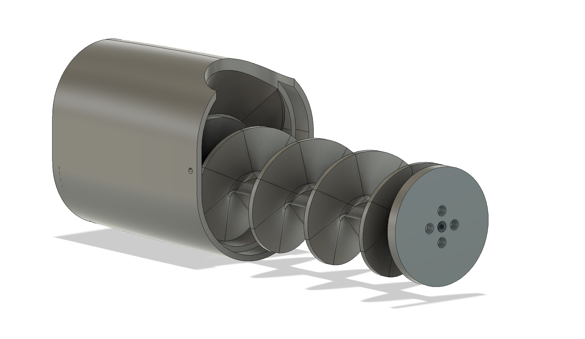
The biggest challenge was the assembly. In order to secure the motor inside the shell, I made a coupling plate that I could attach the motor to, and slide the whole thing into the shell. The motor needed to be coupled with the auger shaft, which was challenging because the auger needed to have a close fit with shell leaving no room to tighten bolts. I added a small hole at the bottom part of the shell which gave access for an Allen key to reach the coupling joint bolts. I only had a flange coupler, so I made a makeshift setup while I wait for the proper bellow sleeve coupling.
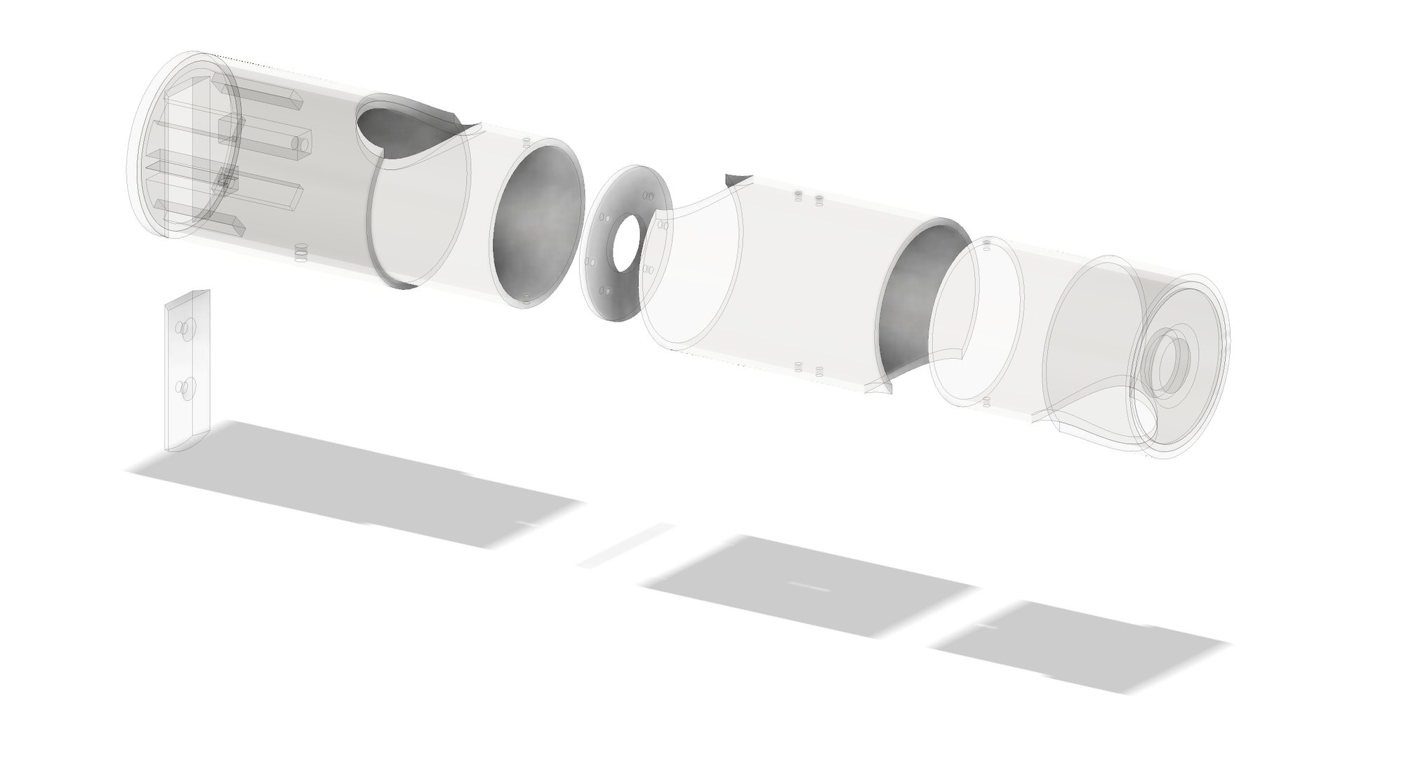
Exploded assembly view, and coupling access whole
Another challenge was wiring. At first I thought of housing most of the component in the shell, but I landed on housing only the motor in the shell and used the wall attachment piece as a way to pass through the motor cable.
Hopper dispenser and wall attachment
I wanted to be able to load the full 4-5 kg roast for dispensing at once, which required both a large enough hopper, and a strong enough attachment to hold that weight. The solution I came up with was attaching a hopper to the wall, so that the shell is not bearing the weight. Printing a hoper that size would have been very time consuming and would require a lot of support material. I opted to use a 18L water bottle instead; I later found out that the 15L ones are cheaper because they don't have a recycling deposit; and I was able to score one out of the neighbour's recycling bin.
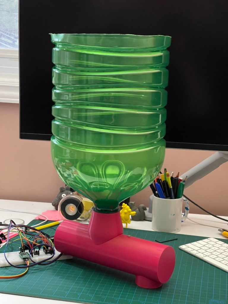
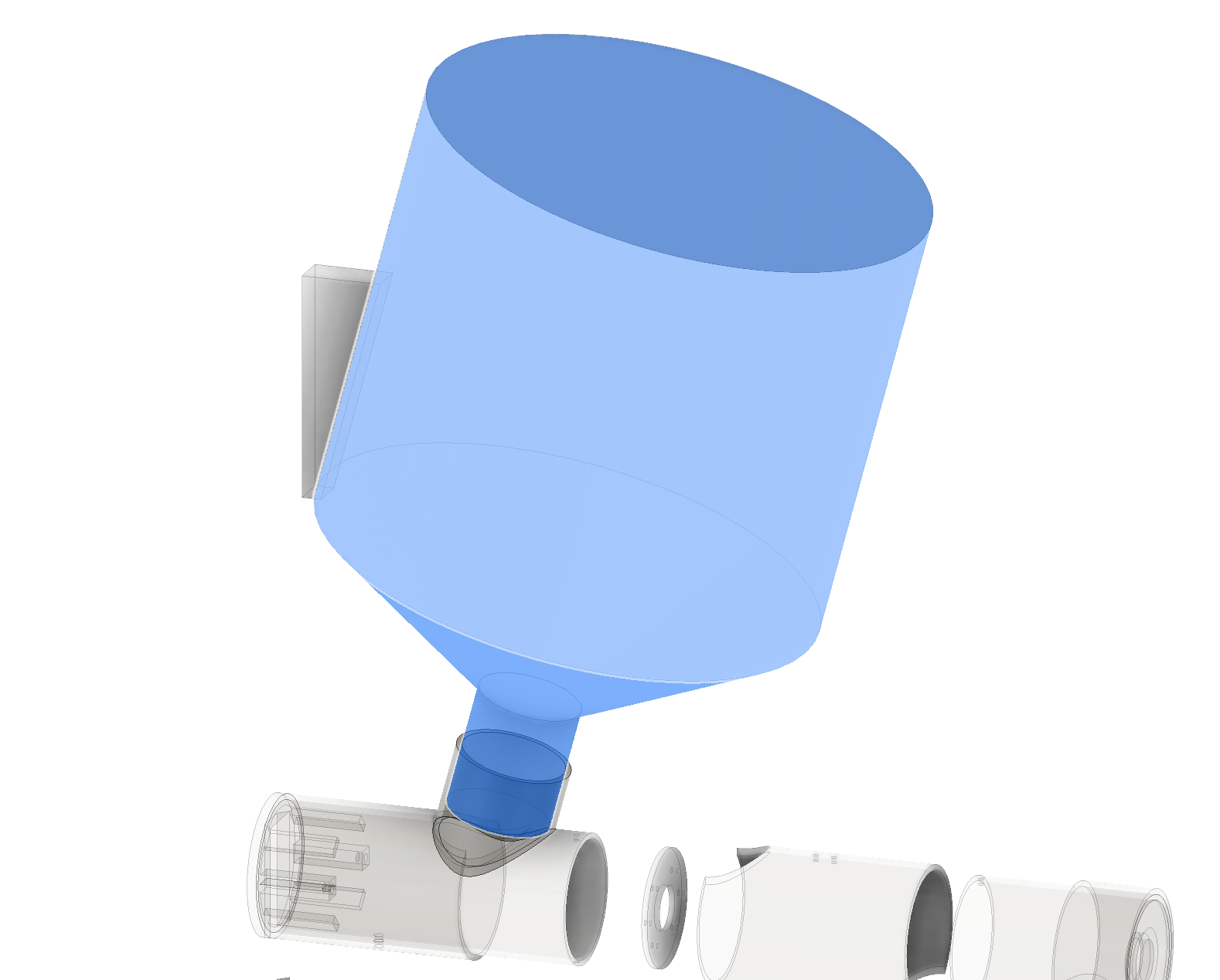
The 15 litre bottle is small enough to be upright, my original design had a larger 18L bottle that would need to be at angle to fit.
Scale
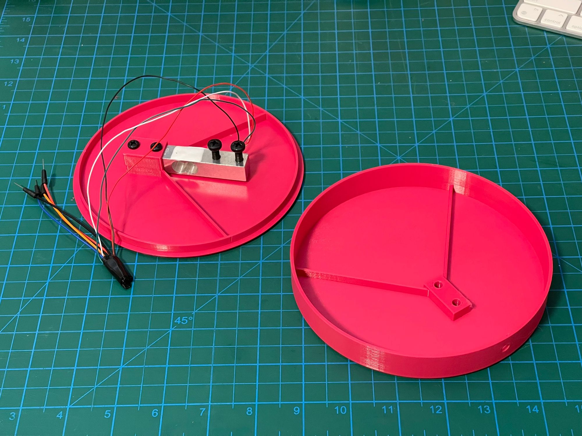
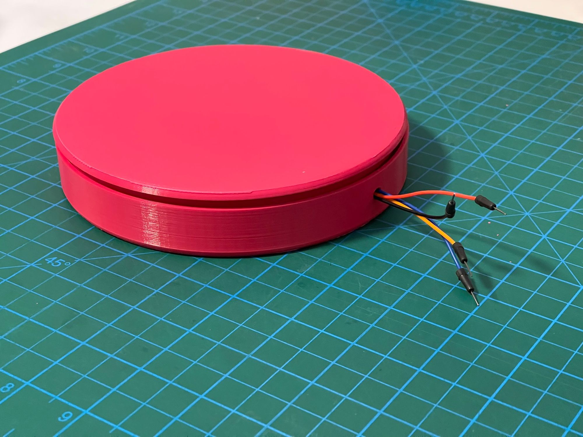
The scale was the first electronic component I built because thought the motor should work fine. What I like about this design is that I was able to use the load cell to hold the two pieces together and to hide the bolts underneath.
Electronics housing
I'll need to figure out where I shove the rat's nest of cables. I haven't decided yet what the interface will look like, and I'm not sure I'll want to do it at all (I'm able to test as is, and I've done enough interface design in my day job).
Code
Below is the code for the combined scale + stepper motor with DRV8825 driver + activation button. I haven't pursued this code any further in terms of optimization or other features, because the scale is too imprecise to be used in the real world (see more notes on that in the testing section).
 brovalex
Testing
I had tested the sub-assembly and circuits individually. There were tons of issues and challenges, which I won't dive into here. Once all the sub-systems were functional, putting it altogether wasn't all that difficult.
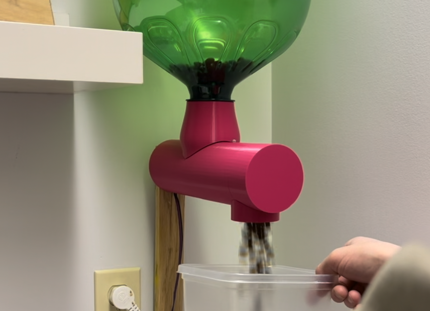
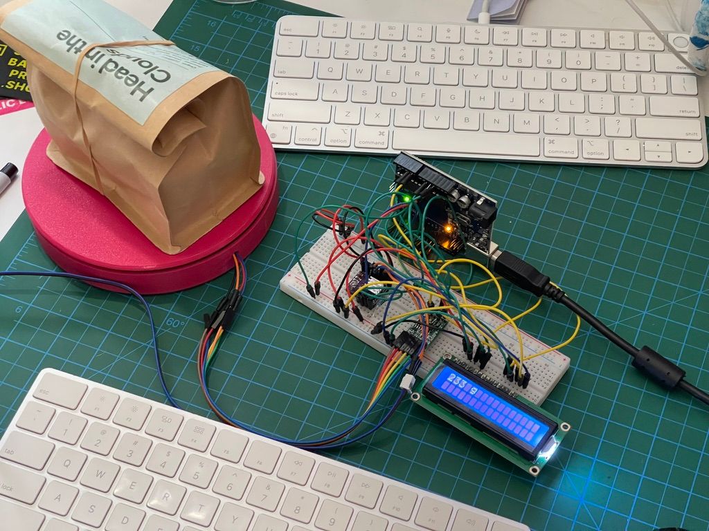
Conceptually the real world test worked as expected: coffee beans are moved really fast, the scale would stop the motor when it reached the desired weight. However, there were two main failures.
Firstly, the scale is terribly inaccurate, and has significant creep (e.g. after a few minutes of use, the reading would climb by 30-50g). Having done further research on these cells, building an accurate scale would be a project of its own, and would definitely not be worthwhile compared to an existing off-the-shelf USB-enabled scale. Since I am using a stepper motor, I decided I could just calibrate the dispenser to a number of steps, and just repeat it for each bag. In some ways, that's actually a more elegant solution in my opinion.
Second, and as predicted by a few friends, the auger gets stuck when fully loaded. When the beans are dropped slowly, there's no issue, but as soon as the auger has to cold start from a full hopper, it gets stuck. I had tried a chamfer on the edge of hole where the auger meets the shell, but that's nowhere near enough to stop the auger from jamming.
Next steps
I have printed a new shell prototype that has generous clearance above the auger. I have yet to assemble it and try it out.
Challenges and learnings
This project has been so far a really good size. I had to learn a lot of basic skills to get started, from soldering to understanding the differences between types of motors, but it was a small enough project I was able to put something together.
- Sourcing electronics: to keep the budget lean, I have order a lot of components from Ali Express. This meant that I would have to plan weeks ahead of time, figure out too late that I'm missing a component, or have to adjust my approach for makeshift fixes.
- Understanding components: figuring out what motor I need or what motor driver to use took a lot of research. Even with extensive research, here were things I didn't know, for example that the DIY load cell would be so inaccurate.
- Electronics as a whole: from issues soldering to understanding differences between types of capacitors for decoupling and filtering, it was a challenge to get my circuitry working. I was fortunate to remember a lot of the basic circuitry and Ohm's Law from university which helped a lot.
- Unexpected issues: quite a few times I had to really scratch my head to figure out what was happening. For example, when I connected the scale and the motor on one circuit, my motor speed reduced significantly; the issue was the my scale was outputting values via the serial port, and the rate there (baud) reduced the step of my motor.
- Arduino basics: this was the main area I wanted to learn about, and certainly had a good run of things to figure out with Arduino programming (in particular the single thread / synchronous loop structure), pin outs, pull down resistors, voltage, and using the various components.
- 3D printing: I haven't planned for this, but this project really upped my 3D printing skills, from designing for different tolerances, to using brass inserts and bolts, I've learned a lot about using Fusion 360 and using my printer.
Many thanks
I've leaned into some friends to help me out at different parts, and learned a ton from them. A big thanks to David for giving me excellent feedback on multiple areas of the design, to Vince for his patience in teaching me so much about electric motors, and Vince, Jimmy, Tom, and others who have fielded questions along the way. And, of course, I would have so many people to thank for all the videos, tutorials, and resources that have been shared online.